
Summary
1. Login Module
1.1 User Login
1.2 Chinese and English Version
2. Homepage
2.1 Announcement Information
2.2 User Basic Information
2.3 System Data
3. Project Summary
3.1 Project Drop-down List
3.2 Left Sidebar
4. Project Management
4.1 Left Project Navigation Bar
4.2 Project Module
4.2.1 Adding a Project
4.2.2 Editing/Deleting Projects
4.3 Network Module
4.3.1 Adding a Network
4.3.2 Editing/Deleting a Network
4.4 Lamp Controller Module
4.4.1 Adding Lamp
4.4.2 Editing Lamp
4.4.3 Delete, Switch Light, Dimming, Parameter Setting, etc
4.4.4 Field Management
4.4.5 Updating Data
4.4.6 Load Settings
5. Daily Record Module
6. Historical Data Module
7. Alarm Information Module
7.1 Marking/Maintenance Scheduling
7.2 Repairer/Maintenance information
7.3 Maintenance Record
7.4 Maintenance Personnel
8. GIS Map Module
8.1 Map Lamp Right-click Editing Function
9. Video Monitoring Module (In Development)
10. Environmental Monitoring Module
11. User Management Module
11.1 Company Management
11.2 Area Management
11.2.1 Add area
11.2.2 Editing/Deleting Areas
11.3 User Management
11.3.1 Adding User
11.3.2 Editing/Disabling user
11.3.3 User Permission Settings
11.4 User Feedback
1. Login Module
1.1 User Login
Log in with username and password, including the remember password function.

1.2 Chinese and English Version
There are Chinese and English version for user login page options.

2. Homepage
2.1 Announcement Information
The top of the homepage is used to display the unprocessed lamp alarm information and the log information such as adding, modifying, instructing, and deleting the user information in the past three days.
2.2 User Basic Information
The user’s avatar, nickname, and user role information are displayed at the top right of the homepage. By clicking the avatar and nickname, user can switch to the user management page to view the account’s detailed information.
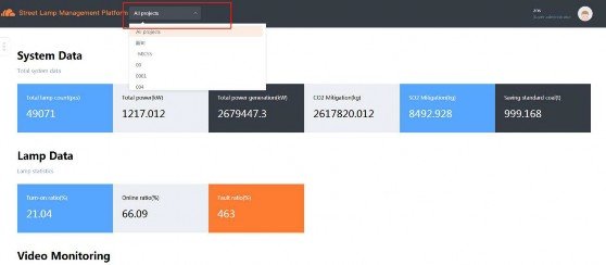
2.3 System Data
The page displays the project managemnet, alarm maintenance, video surveillance and weather monitoring,etc.

3. Project Summary
The project summary page is used to display project system data, lamp data, video surveillance data, and environmental monitoring data (not yet added).
3.1 Project Drop-down List
Above the project summary page is the project drop-down list for selecting to view project data.
3.2 Left Sidebar
There is a button on the left side of the project summary page to show the hidden left sidebar. There are recent alarm data and log information in it. Here only shows part of latest data, for all please view the data on the alarm information page and the log information page.

4. Project Management
4.1 Left Project Navigation Bar
On the left side, there is a project navigation bar for switching the currently displayed project. The navigation bar has a search function that allows user to find data by entering the company name.


4.2 Project Module
4.2.1 Adding a Project
There is an Add Project button on the right side of the project management page. Clicking will switch to the New Project page, as shown below. An input box with a ‘*’ in the page is indicated as a mandatory ption. The company, project area, project province, and project time zone will pop up a drop-down lists for options.
Note: In the newly added company, the project area and project provinces here may be empty. If it is empty, please modify the area and province on the right side of the company information on the user management page.

4.2.2 Editing/Deleting Projects
There is an Edit Project button in the project management page, and clicking will switch to the following page. The information in the page is the current project information. The user can directly modify it, click Save button after the modification, and a successful prompt indicates that the modification is successful. Next to the Save button is a Delete Project button for deleting projects.
Note: When deleting a project, the project-related data such as lamp, network, area, province, video monitor, and environmental monitoring will all be deleted. Please use it with caution.


4.3 Network Module
4.3.1 Adding a Network
In the project management page, there is a Add network button for creating a network. The system will automatically search the network around, user can also add it by himself.


4.3.2 Editing/Deleting a Network
Click the button near the All lamp and user can see the network list and can click it to go to view the network details. There is an Edit Network button on the right, user can click it to edit or delete the network.
Note: Deleting a network will deletes the lamp and lamp related data under the network. Please use with caution.


4.4 Lamp Controller Module
4.4.1 Adding Lamp
There are two ways user can add lamps on the project management page, as shown in Figure 12. Clicking Add lamp will switch to the Figure 13 for adding single lamp controls. And if many lamps, user can click the Batch add to download an excel file and then fill in all the lamps information and upload the file to add batch lamps.

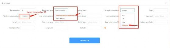

Note:
1) LoRaWAN, NBiot, GPRS One-to-one module device type are direct device
2) Network type:
LoRaWAN module: LoRa
NBIot module: NB
GPRS one-to-one module: UDP
4.4.2 Editing Lamp
There is a Modify button on the operation column on the right side of the lamp list. User can click this button to view the lamp related data can be directly modified here.


4.4.3 Delete, Switch Light, Dimming, Parameter Setting, etc.
There is a Batch button above the lamp list. User can click this button to switch to the batch lamp list. Select the lamp user want to operate, then select the operation in the operation list, and finally click Save to modify.


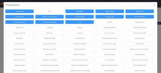
4.4.4 Field Management
There is a Field Management button in the upper right corner of the project management page. User can click this button to switch to the field management page, in which you can select the data displayed in the lamp list.

4.4.5 Updating Data
There is an Update data button in the upper right corner of the project management page. Before updating the data, user need to select the lamp to be updated in the lamp list, and then click the Update button. The update will be launched in the background. One lamp can only be operated once within 2 minutes.

4.4.6 Load Settings
Select the lamp to be operated, click the load settings button on the project management page, and jump to the load management page in Figure 20 to add or modify the load settings.


5. Daily Record Module
Figure 21 shows the operation log page for displaying user action records. There is a drop-down filter at the top right for selecting the operation log type. The Export button allows the log content to be exported in Excel form. The upper left search box can be used to search for the user ID, user name, and operation content.

6. Historical Data Module
Figure 22 shows the historical data page for displaying historical data such a power generation and consumption, current, voltage and temperature. Filter by the drop-down list in the upper right. The search box at the top left provides searching function for the lamp number.

The “See Selected lamps” button in Figure 22 allows user to view individual or multiple lamp details. First select the lamp you want to view in the lamp list, user can select up to 4 lamps here, then click the “See Selected lamps” button to switch to the data comparison page. In the lower right corner, user can choose to view the data for a certain period of time.

7. Alarm Information Module
Figure 24 shows the alarm information homepage. The page is used to view alarm information, historical alarms and inspection time. The alarm information is the default selected page, which is used to display the latest alarm information of the lamp. Each lamp has one and only one information. On the historical alarm page, all alarm information of the lamp is displayed.

7.1 Marking/Maintenance Scheduling
There is a button on the right side of the alarm information homepage to show the hidden right sidebar. The maintenance schedule is used to dispatch maintenance personnel to process alarm information. After the maintenance personnel process the alarm information, the alarm information needs to be marked as processed. Figure 25 shows the maintenance schedule.

7.2 Repairer/Maintenance information
After the mark is processed, the right action bar will be changed to the Operator and Maintenance information, which is used to view the history and maintenance records of the current lamp.
Note: The operator and maintenance information here may be empty. User can switch to the maintenance record page through the right sidebar, which is used for adding maintenance record.


7.3 Maintenance Record
Figure 28 shows the maintenance record page. Click the button in the upper right corner to switch to the add page. User can click the View all button to switch to the maintenance record page to modify the maintenance record.

7.4 Maintenance Personnel
Figure 29 shows the service personnel page and the right button is used to add maintenance personnel. The user can search for the name of the maintenance person and the ID of the service person through the search box at the upper left, and the first letter of the service person at the upper right.


Click on the maintenance personnel in the list, and the maintenance personnel details and maintenance record information will be displayed below. As shown in Figure 31, the Edit Data button on the lower right is used to modify the service personnel information. The middle list is the maintenance record information.

8. GIS Map Module
Figure 32 shows the top page of the GIS map. The left button can be used to filter the lamps in the map page, and the left side bar can be used for project selection. Lamps, projects, and monitoring information are displayed in the right sidebar.

8.1 Map Lamp Right-click Editing Function
Figure 33 shows the map lamp right-click editing page. Select the lamp and then user can click the right mouse button to move or delete the lamp.


9. Video Monitoring Module (In Development)
10. Environmental Monitoring Module
Figure 37 shows the home screen of the video monitor, and user can add monitoring to the upper right. Items can be filtered in the left sidebar.

11. User Management Module
Figure 38 shows the user management homepage, and user can modify the user information on the current page. Figure 39 shows the Modify User Password page.


11.1 Company Management
Figure 40 shows the company information interface. The right side shows the current company area information. Click the View Company button in the figure below, and the company list will pop up, as shown in Figure 41. Clicking on Add company customers in the list will bring up the Add Company page, which allowsb user to add a company.
Note: This operation is only available to the system administrator.


11.2 Area Management
11.2.1 Add area
There is an Add area button on the right side of the company information. User can click it to switch the add area Page. As shown in Figure 42, user can choose to add a area or add a province in the Page.

11.2.2 Editing/Deleting Areas
Click the area name in the right area list to switch to the Edit area interface, which contains the Delete Area function. As shown in Figure 43:

11.3 User Management
11.3.1 Adding User
In the company interface, there is a company sub-account management module, the user manages the account information under the current company, the user created by the system administrator is the company administrator, and the user created by the company administrator is the company customer. The following figure shows creating a user page.

Click the selection item in Figure 44 to pop up the following interface. The administrator can select the user project permissions according to the actual situation. When user creates a company administrator, if he doesn’t select specific permissions, the company administrator has all permissions by default.

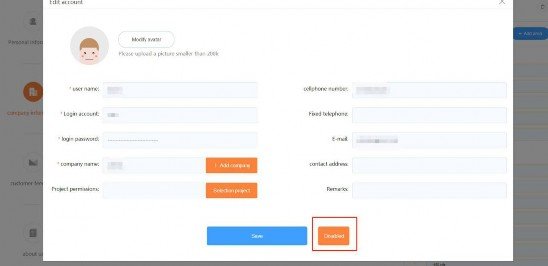
11.3.2 Editing/Disabling user
Click the user edit button on the company information page to switch the us edit interface, as shown in Figure 46, where user can modify the user information. There is a disable button at the bottom of the page, which is used for disabling this account.
11.3.3 User Permission Settings
Click the “User Permissions” button on the company information page to switch to the following page to view/modify user permissions and user project permissions.
Note: User cannot modify the permissions between user at the same level. Only the upper-level user can modify the lower-level user rights. The administrator has all the permissions by default. The company customers have all viewing rights by default.
11.4 User Feedback
Figure 47 shows the user feedback page.